Antennas
Links:
AAE | Artex | Becker | Comant | Walter Dittel | ICOM | Larsen | RAMI
Overview
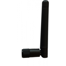
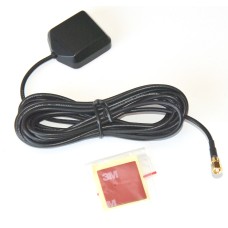
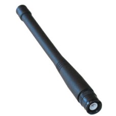
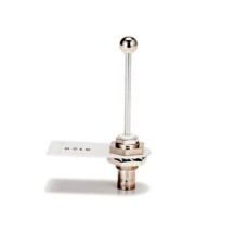
I offer a wide variety of antenna types for the many different aviation communication applications.
Transponder and Radio Antenna Cables
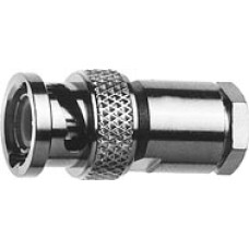
I offer transponder antenna cables made by Larry Goddard in several lengths. They include a TNC connector for connection to the transponder and a BNC connector for connection to a transponder antenna. They are available in 3 m (9.84 feet) and 5 m (16.4 feet) lengths. I also offer radio antenna cables from Larry Goddard in several lengths. They include BNC connectors on both ends, or a BNC connector at the radio end and bare leads (NC for "No Connector") at the antenna end.
Transponder Antennas
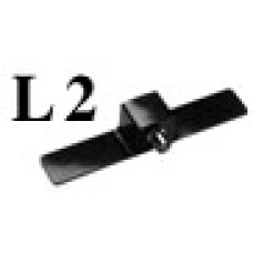
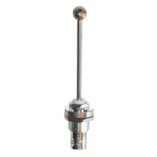
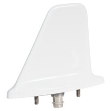
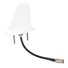
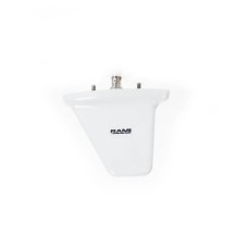
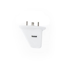
Several transponder antenna options are listed on the Antennas page. The RAMI rod style and "shark fin" styles are the most popular. I recommend the shark fin style because I recall from my fluid dynamics courses that the two worst types of bodies in regard to drag are spheres and cylinders. For installations inside fiberglass, wood and fabric gliders, or in the vertical fin in carbon fiber gliders (with the fin made of fiberglass) you may want to consider the L2 antenna from AAE.
Frequency Overview
Aviation Radio Communication Band: 118.000 to 136.975 MHz
Aviation Radio Navigation Band: 108.000 to 117.975 MHz
Weather: 161.650 to 163.275 MHz
ELTs (standard): 121.5 and 243.0 MHz
ELTs (new): 121.5 and 406.028 MHz
DME: 950 to 1220 MHz
Transponders: 1030 and 1090 MHz
Antenna Length
Aircraft radio antennas come in several length styles: 1/4 wave, 1/2 wave and 5/8 wave are common. To calculate the length of antenna required for a specific frequency you can use the formula below. However, the calculations below are approximate only. Other factor such as the distance to the ground plane, length of the antenna cable and antenna end effects make it impossible to accurately calculate the length of any antenna. The easiest way to test an antenna is to use an VSWR meter or SWR analyzer such as the MFJ-259B from MFJ Enterprises, Incorporated. I use the MFJ-259B to accurately test and set the length of all the adjustable length antennas I sell. Note: When testing the antenna length it is important that the testing be done with the same or similar ground plane that it will be used with. The antenna cable length is also very important. All tests done by Cumulus soaring are done using a specified cable length and using a good ground plane. Magnet base antennas are tested on the roof of my sedan.
- Antenna Length (meters) = 300 / Freq (in MHz) * length fraction (1/4 wave, 1/2 wave, 5/8 wave, etc.)
- Antenna Length (inches) = 300 / Freq (in MHz) * 3.281 ft/m * 12 in/ft * length fraction (1/4 wave, 1/2 wave, 5/8 wave, etc.)
- Example: 300 / 123.4 MHz *3.281 *12 * 1/4 = 23.93 inches
Since every frequency has a unique optimal antenna length you will need to find a compromise on the antenna length. It will work well for the frequencies near the frequency it is tuned to.
Tips for Ground Planes for Aircraft Radio Antennas
Most radio antennas require a ground plane. The AV-534 is a good example of an antenna that performs best with a ground plane. A ground plane is a metal surface that is connected to the antennas ground (common). There is no need for a ground plane when mounting an antenna on a metal aircraft, but it can be tough to accommodate in a fiberglass aircraft such as a sailplane.
Note: Radio antennas can be mounted inside a fiberglass aircraft, but they would not work well if mounted inside a carbon fiber aircraft.
Below is a note from RAMI about ground planes for aircraft radio antennas.
A proper ground plane is one that extends 1/4 wavelength (at the operating frequency) outward in all directions from the feed point or base of the antenna. 1/4 wavelength at aircraft com frequencies is approximately 24 inches. So the ground plane would be approximately 4 ft. X 4 ft. (or 4 ft. diameter) conductive surface with the antenna mounted in the center. You can also accomplish this with (2) four foot ( 1.22 m) long conductive wires running perpendicular to each other and electrically connected to the shield of the transmission line at the base of the antenna at their mid points. Similar to a base station antenna seen at an airport terminal building. The wires can be run inside the fuselage forward and aft and down the inside wall.
Sincerely,
Ben Ennenga
Engineering Manager / GAA Product Line Manager
RAMI
Tips for Ground Planes for Transponder Antennas
I talked to Ben Ennenga at RAMI about transponder antenna ground planes. Some interesting notes from that conversation are below. Thank you Ben for the friendly and helpful support!
- A ground plane is required (of course) with both rod style and blade style transponder antennas.
- The smallest recommended ground plane would be 12 inches in diameter (6 inches radius).
- A ground plane works about equally well regardless of whether it is made from a solid plate (such as aluminum) or instead made using 2 wires in a "+" arrangement. In either case, the radius should be at least 6 inches.
- When working with carbon fiber glider fuselages, the antenna must be mounted on the outside of the fuselage, but it is OK to mount the ground plane on the inside.
- The mounting screws for the RAMI AV-74 antenna are connected to the antenna ground. Therefore, you can connect the ground plane to either or both of the mounting screws.
- It is OK for the ground plane wires ("+" configuration) to curve and follow the inside of the glider fuselage.
AAE-L2
L2 Transponder AntennaDesigned for use with transponders.The L2 is configured to allow the..
$99.00
AAE-VHF-5I
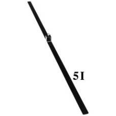
5I VHF Communication and Navigation Antenna - Perpendicular ConnectorDesigned for use with avia..
$149.00
AAE-VHF-5T
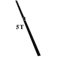
5T VHF Communication and Navigation Antenna - Horizontal ConnectorDesigned for use with aviatio..
$149.00
Becker-1A005
VHF Antenna for Installation in Fiberglass Aircraft118 to 136 MHzThis antenna was developed especial..
$350.00
Comant - CI-101
Antenna, Transponder, StubThis unit is a bit on the expensive side. I recommend the RAMI-..
$134.00
Comant - CI-105
Antenna, Transponder, Blade StyleThis unit is a bit on the expensive side. I recommend the&nbs..
$185.00
Comant - CI-105-9
Antenna, Transponder, Blade Style with Remote ConnectorThis unit is a bit on the expensive side.&nbs..
$299.00
Dittel-E59767
Antenna connector, BNC plugSolder type, for RG-58 cableThis is an extremely nice BNC connector. Sold..
$14.95
Dittel-F10345
Whip AntennaFor use with Dittel 10013 Portable Case 70 PS and 10360 Portable Case 70 PCLead time: 2 ..
$150.00
Dittel-W00114
Rod antenna, swivel typeFor mounting on a car or recreational vehicle. Rod Length: 19.5" (0.49..
$120.00
EW-Antenna
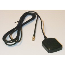
GPS Antenna for EW microRecorderCable Length: 5 ft (1.52 m)Cable Type: RG174Connector Type: SMA..
$25.00
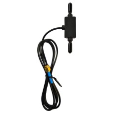
FLARM-Ant-ADSB-Dipole-SMA
PowerFLARM Dipole ADS-B Antenna with Standard Polarity ConnectorConnects directly to a PowerFLARM Fu..
$40.00
FLARM-Ant-ADSB-Rod-SMARP
PowerFLARM Rod Style ADS-B Antenna with Reverse-Polarity ConnectorWorks on PowerFLARM Portable.Note:..
$43.00
FLARM-Ant-FLARM-Dipole-SMA-US
PowerFLARM Dipole FLARM Antenna with Standard-Polarity ConnectorFor use on "B" FLARM port on PowerFL..
$40.00
FLARM-Ant-FLARM-Dipole-SMARP-EU
PowerFLARM Dipole FLARM Antenna with Reverse-Polarity Connector - Standard Antenna LengthFor us..
$45.00
FLARM-Ant-FLARM-Dipole-SMARP-US
PowerFLARM Dipole FLARM Antenna with Reverse-Polarity Connector - Standard Antenna LengthFor us..
$50.00
FLARM-Ant-FLARM-Dipole-SMARP-US-Long
PowerFLARM Dipole FLARM Antenna with Reverse-Polarity Connector - Long Antenna LengthThis anten..
$25.00
FLARM-Ant-FLARM-Rod-SMARP
PowerFLARM Rod Style FLARM Antenna with Reverse-Polarity ConnectorWorks on PowerFLARM Portable and P..
$43.00
FLARM-Ant-FLARM-Shark-BNC
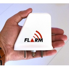
PowerFLARM FLARM Antenna, Shark Fin - With FLARM LogoWorks great as an external FLARM A transmit/rec..
$270.00
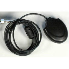
FLARM-Ant-GPS-MCX
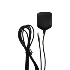
Remote GPS Antenna for PowerFLARM Core and PowerFLARM PortableOptional external GPS antenna for Powe..
$50.00
FLARM-Ant-GPS-SMC
Remote GPS Antenna for PowerFLARM FusionExternal GPS antenna for PowerFLARM Fusion, with SMC connect..
$40.00
Icom-IC-FA-B02AR
AntennaSame as supplied with the transceiver. For IC-A4, A5, A6, A14, A14S, A23, A24, and A25 radios..
$40.00
Larsen-BS-5-8
Larsen Base Station Antenna - 5/8 Wave - Cable with BNC Connector IncludedThis is a very nice base s..
$168.00
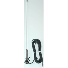
Larsen-MB-1-4
Larsen Magnet Base Antenna - Quarter WaveThis is a very nice magnet base antenna for use on your car..
$89.00
Larsen-MB-5-8
Larsen Magnet Base Antenna - 5/8 WaveThis is a very nice magnet base antenna for use on your car, tr..
$128.00
LXNAV-Ant-ADSB-Rod-Rt-Angle
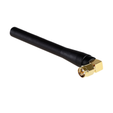
Antenna, ADS-B, Rod with Standard-Polarity SMA ConnectorLXNAV ADS-B Antenna with standard-polarity S..
$20.00
LXNAV-Ant-GPS-SMC
GPS Antenna with SMC ConnectorGPS Antenna, with SMC connector, for use with LXNAV S10, S100, LX80x0,..
$50.00
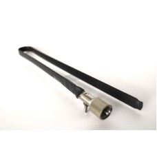
NAV-151
Antenna, FlexibleNot Currently Available118 to 136 MHz (Aircraft Radio Band), Connector: BNC, maleNo..
$0.00
RAMI-AV-22
RAMI AV-22 Rod Style Transponder AntennaThe AV-22 is a transponder antenna which utilizes a "BNC" co..
$130.00
RAMI-AV-534
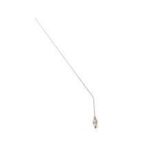
Antenna, Bent Rod Style, 1/4 Wave118 to 136 MHz (Aircraft Radio Band)The AV-534 is a heavy-duty stai..
$125.00
RAMI-AV-74
RAMI AV-74 Blade Style Transponder or DME AntennaNote: Most glider pilots prefer the AV-74-1 below b..
$180.00
RAMI-AV-74-1
RAMI AV-74-1 Blade Style Transponder or DME AntennaThis antenna is like the AV-74 - but with longer ..
$185.00


